Introduction: (Initial Observation)
Levees and floodwalls are among the main structures used to confine the river water and prevent flooding the adjoining countryside. Levees and floodwalls are especially important when the water level rises due to heavy rain and storm. When levees and floodwalls fail, the disaster strikes and rushing water floods the area resulting death and destruction of houses, farms and industries.
In the last days of August 2005 a category 5 tropical store named hurricane Katrina moved inland in the Mississippi area. Its storm surge soon breached the levee system that protected New Orleans from Lake Pontchartrain and the Mississippi River.

Most of the city was subsequently flooded mainly by water from the lake. Heavy damage was also inflicted onto the coasts of Mississippi and Alabama, causing Katrina to become the most destructive and costliest natural disaster in the history of the United States.
Louisiana flood resulted more than 1000 death and displacement of about one million people.
Further inspections and investigations have shown that the breach of floodwalls in three different areas have been the main cause of city wide flooding the New Orleans.
Could the Louisiana flood be prevented by reinforcing the levees and floodwalls?
The disaster in New Orleans have made scientists and engineers think about possible ways of reinforcing levees and floodwalls in order to prevent future disasters. In this project we will study the of reinforcing of levees and floodwalls with steel beams.
Project Plan:
-
- Propose a reason why you have selected this topic for your science project. This is what you usually write as the introduction in your project report to show your initiative.
- Gather information about levees and floodwalls: What they are? How they are made? Why are they needed? What is the history of using levees? Why and how they fail?
- Propose improvement ideas and select one of such ideas to be experimented during this project.
- Design an experiment.
- Perform the experiment and record the data.
- Analyze the experiment data and use them in drawing a conclusion.
Information Gathering:
Find out about levees. Read books, magazines or ask professionals who might know in order to learn about levee design and effect of different design elements on the strength of levees. Keep track of where you got your information from.
Following are samples of information you may find.
Levee
From Wikipedia, the free encyclopedia.
This article is about the type of dam. See also Levee (event)
A levee, levée (from the feminine past participle of the French verb lever, “to raise”), floodbank or stopbank is a natural or artificial embankment or dike, usually earthen, which parallels the course of a river. The word levee seems to have come into English through its use in colonial Louisiana.
Contents
Artificial levees

The main purpose of artificial levees is to prevent flooding of the adjoining countryside; however, they also confine the flow of the river resulting in higher and faster water flow.
Levees are usually built by piling earth on a cleared, level surface. Broad at the base, they taper to a level top, where temporarily embankments or sandbags can be placed. Because flood discharge intensity increases in levees on both river banks, and because silt deposits raise the level of riverbeds, planning and auxiliary measures are vital. Sections are often set back from the river to form a wider channel, and flood valley basins are divided by multiple levees to prevent a single breach from flooding a large area.
Artificial levees require substantial engineering. Their surface must be protected from erosion, so they are planted with vegetation such as Bermuda grass in order to bind the earth together. On the land side of high levees, a low terrace of earth known as a banquette is usually added as another anti-erosion measure. On the river side, erosion from strong waves or currents presents an even greater threat to the integrity of the levee. The effects of erosion are countered by planting with willows, weighted matting or concrete revetments. Separate ditches or drainage tiles are constructed to ensure that the foundation does not become waterlogged.
The first levees were constructed over 3,000 years ago in ancient Egypt, where a system of levees was built along the left bank of the River Nile for more than 600 miles (966 km), stretching from modern Aswan to the Nile Delta on the shores of the Mediterranean. The Mesopotamian civilizations and ancient China also built large levee systems. Because a levee is only as strong as its weakest point, the height and standards of construction have to be consistent along its length. This requires a strong governing authority to guide the work, and may have been a catalyst for the development of systems of governance in early civilizations.
In modern times, prominent levee systems exist along the Mississippi River and Sacramento Rivers in the United States, and the Po, Rhine, Loire, Vistula, and Danube in Europe.
The Mississippi levees represent one of the largest such systems found anywhere in the world. They comprise over 3,500 miles (5,600 km) of levees extending some 1,000 miles (1,600 km) along the Mississippi, stretching from Cape Girardeau, Missouri to the Mississippi Delta. They were begun by French settlers in Louisiana in the 18th century to protect the city of New Orleans. The first Louisianian levees were about 3 feet (0.9 m) high and covered a distance of about 50 miles (80 km) along the riverside. By the mid-1980s, they had reached their present extent and averaged 24 feet (7 m) in height; some Mississippi levees are as much as 50 feet (15 m) high. The Mississippi levees also include some of the longest continuous individual levees in the world. One such levee extends southwards from Pine Bluff, Arkansas for a distance of some 380 miles (611 km).
Natural levees
The ability of a river to carry sediment varies very strongly with its speed. When a river floods over its banks, the water spreads out, slows down, and deposits its load of sediment. Over time, the river’s banks are built up above the level of the rest of the floodplain. The resulting ridges are called natural levees.
When the river is not in flood state it may deposit material within its channel, raising its level. The combination can raise not just the surface, but even the bottom of the river above the surounding country. Natural levees are especially noted on the Yellow River in China near the sea where oceangoing ships appear to sail high above the plain on the elevated river. Natural levees are a common feature of all meandering rivers in the world.
Levees in tidal waters
The same basic process occurs in tidal creeks when the incoming tide carries mineral material of all grades up to the limit imposed by the energy of the flow. As the tide overflows the sides of the creek towards high water, the flow rate at the brink slows and larger sediment is deposited, forming the levee. At the height of the tide, the water stands on the salt-marsh or flats and the finer particles slowly settle, forming clay. In the early ebb, the water level in the creek falls leaving the broad expanse of water standing on the marsh at a higher level.
The area of water on the marsh is much greater than the water surface of the creek so that in the latter, the flow rate is much greater. It is this rush of water, perhaps an hour after high water, which keeps the creek channel open. The cross-sectional area of the water body in the creek is small compared with that initially over the levee which at this stage is acting as a weir. The deposited sediment (coarse on the levee and on the mud flats or salt-marsh) therefore tends to stay put so that, tide by tide, the marsh and levee grow higher until they are of such a height that few tides overflow them. In an active system, the levee is always higher than the marsh. That is how it came to be called “une rive levée” or raised shore.
Levee breaches
The Great Mississippi Flood occurred in 1927 when the Mississippi River breached levees and flooded 27,000 square miles, killing 246 people in seven states and displacing 700,000 people.
In the North Sea flood of 1953, levees and flood defenses collapsed in the United Kingdom and the Netherlands, killing over 2,100 people.
During the passage of Hurricane Katrina in August 2005, floodwaters breached levees protecting New Orleans, causing catastrophic flooding and resulting in the total evacuation of the city (effects on levees are discussed further in Effect of Hurricane Katrina on New Orleans).
The floodwall on the 17th Street Canal levee was destined to fail long before it reached its maximum design load of 14 feet of water because the Army Corps of Engineers underestimated the weak soil layers 10 to 25 feet below the levee, the state’s forensic levee investigation team concluded in a report to be released this week.
That miscalculation was so obvious and fundamental, investigators said, they “could not fathom” how the design team of engineers from the corps, local firm Eustis Engineering and the national firm Modjeski and Masters could have missed what is being termed the costliest engineering mistake in American history.
Mystery surrounds floodwall breaches
Could a structural flaw be to blame?
By John McQuaid
Staff writer
One of the central mysteries emerging in the Hurricane Katrina disaster is why concrete floodwalls in three canals breached during the storm, causing much of the catastrophic flooding, while earthen hurricane levees surrounding the city remained intact.
Question/ Purpose:
What do you want to find out? Write a statement that describes what you want to do. Use your observations and questions to write the statement.
The purpose of this project is to design external steel reinforcement structures for existing floodwalls.
For each possible design we will perform experiments to determine the effect of reinforcement on the strength of flood wall and identify the best reinforcement method by comparing the test results.
Reinforcement methods that we will try are: vertical bar reinforcement, L shape reinforcement, Triangular reinforcement, and rectangular reinforcement. Following are a brief description of each method.
Vertical bar reinforcement: In this method we dig a deep hole next to the base of the wall and insert a steel beam in the hole while touching the wall all along its length. We then secure the steel bar in place by pouring concrete in the hole.

L shape reinforcement: In this method we install an L shape steel structure to hold the wall, the bottom part of the L shape structure will be placed in a shallow canal and hold in place by pouring concrete in the canal.

Triangular reinforcement: In the triangular reinforcement method a triangle structure will be installed to hold the wall.

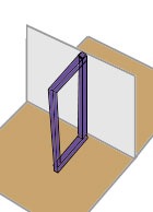
Rectangular reinforcement: In the rectangular method, a rectangular structure will be installed to reinforce the wall.
Steel cable reinforcement: In this method a steel cable connects the top of the wall to a steel rod inserted in the ground in the river side. If the ground is soft, the rod may be secured by pouring concrete around it.
In an experiment model you may use a nail as the rod and a tread or thin wire as the steel cable. The rod must be inserted angular so that the steel cable connect to that in a right angle. In this way the rod will not be pulled out by the force of the wall.

You may come up with many other reinforcement ideas and name them as you like and include a description of each method.
Identify Variables:
When you think you know what variables may be involved, think about ways to change one at a time. If you change more than one at a time, you will not know what variable is causing your observation. Sometimes variables are linked and work together to cause something. At first, try to choose variables that you think act independently of each other.
Independent variable (also known as manipulated variable) is the reinforcement design used to increase the strength of a floodwall. Possible values are (vertical bar reinforcement, L shape reinforcement, Triangular reinforcement, and rectangular reinforcement.)
Dependent variable (also known as responding variable) is the strength of floodwall.
Constants are the type of materials and production costs. We try to use the same type and the same amount of materials in different designs; however, we will finally calculate the efficiency of each method by dividing the production cost by the increase in the strength.
Hypothesis:
Based on your gathered information, make an educated guess about what types of things affect the system you are working with. Identifying variables is necessary before you can make a hypothesis.
This is a sample hypothesis:
Among the four reinforcement methods I am testing, I think the triangular reinforcement will provide the highest strength. My hypothesis is based on my gathered information, observation of bridges and other steel structures and a common sense.
Experiment Design:
Design an experiment to test each hypothesis. Make a step-by-step list of what you will do to answer each question. This list is called an experimental procedure. For an experiment to give answers you can trust, it must have a “control.” A control is an additional experimental trial or run. It is a separate experiment, done exactly like the others. The only difference is that no experimental variables are changed. A control is a neutral “reference point” for comparison that allows you to see what changing a variable does by comparing it to not changing anything. Dependable controls are sometimes very hard to develop. They can be the hardest part of a project. Without a control you cannot be sure that changing the variable causes your observations. A series of experiments that includes a control is called a “controlled experiment.”
Experiment 1: External reinforcement of floodwalls using steel beams
Introduction: A rush of moving water from a storm surge or from a flooded river has an enormous force caused by the mass of moving water and its speed. In a small scale laboratory test we may substitute such force by any moving heavy object. In this experiment we will test the effect of different steel reinforcement designs on the strength of levees and floodwalls. Minor leaks are never a concern. Cities that are below sea level or are protected by levees and floodwalls are equipped with pumps to discharge the water leaked into the area from levees or from rising underground waters.
Materials:
-
- One 2″ thick Styrofoam board. (Standard boards are 4’x8′, half a board is enough for all your experiments) (Actual thickness is slightly less than 2″)
- One 1″ thick Styrofoam board. (half a board is enough for all your experiments. Smaller pieces are also sold in the insulation materials section of hardware stores) (Actual thickness is slightly less than 1″)
- Utility knife with a long retractable blade.
- Ruler and meter stick or measuring tape
Procedure:
- Cut a 2′ x 3′ piece from the 2″ thick Styrofoam board to be used as an unstable ground for installing floodwalls.
- Cut an 8″ x 24″ piece of 1″ thick Styrofoam board to be used as a floodwall.
- Cut 6 pieces of 2″ x 8″ from the 1″ thick Styrofoam board as supporting columns.
- Use wood glue to connect the supporting columns on two sides of the floodwall. Wait until the glue is dry.
- Slightly glue the bottom of the wall and fully glue the bottom of the supporting columns and then place the floodwall on the center of the 2 x 3 ground board and hold it in place for a few hours until the glue is fully dry and hard. You may use books or other objects to hold the dry wall in place until the glue id dried.
6. To measure the strength of this wall, hold the ground board vertically so the flood wall will remain horizontal. In this condition place masses (small stones) on the floodwall. Continue to add masses until the wall brakes. Record the total mass that broke the wall. This will be the breakage force for the wall without any reinforcement.
7. Repeat the steps 1 to 6 with any additional reinforcement ideas you may have and compare the results.

Following are some reinforcement ideas for floodwalls:
Triangular back support:
Triangles are among the strongest engineering structures often used in the design of bridges. Triangular structures can change the direction of the force.
When a surge of water heats the wall, the triangular structure in the opposite side changes the force to a downward force trying to push the other corner of the triangle into the ground.

For a model of floodwall made from Styrofoam, you may use strips of bass wood (available at craft stores) as a substitute for steel. You may also use other wood moldings that are available in hardware stores. Bass wood is easier to cut and some use utility knives to cut the sticks of basswood.

Many other reinforcement designs may be made and tested with the same method.
After you complete your experiments and measure the breakage force with different reinforcement designs, you may have a results table like this:
| Reinforcement method | Maximum Strength of the wall |
| None | |
| Vertical post | |
| L shape structure | |
| Triangular structure | |
| Rectangular structure | |
| Steel cable |
Forces may be in kilograms, Newtons or pounds.
Materials and Equipment:
List of materials may vary depending on the changes you may make in the procedures and the materials that are available in your area.
Results of Experiment (Observation):
Experiments are often done in series. A series of experiments can be done by changing one variable a different amount each time. A series of experiments is made up of separate experimental “runs.” During each run you make a measurement of how much the variable affected the system under study. For each run, a different amount of change in the variable is used. This produces a different amount of response in the system. You measure this response, or record data, in a table for this purpose. This is considered “raw data” since it has not been processed or interpreted yet. When raw data gets processed mathematically, for example, it becomes results.
Calculations:
If you do any calculations, write your calculations in this section of your report.
Summary of Results:
Summarize what happened. This can be in the form of a table of processed numerical data, or graphs. It could also be a written statement of what occurred during experiments.
It is from calculations using recorded data that tables and graphs are made. Studying tables and graphs, we can see trends that tell us how different variables cause our observations. Based on these trends, we can draw conclusions about the system under study. These conclusions help us confirm or deny our original hypothesis. Often, mathematical equations can be made from graphs. These equations allow us to predict how a change will affect the system without the need to do additional experiments. Advanced levels of experimental science rely heavily on graphical and mathematical analysis of data. At this level, science becomes even more interesting and powerful.
Conclusion:
Using the trends in your experimental data and your experimental observations, try to answer your original questions. Is your hypothesis correct? Now is the time to pull together what happened, and assess the experiments you did.
Related Questions & Answers:
What you have learned may allow you to answer other questions. Many questions are related. Several new questions may have occurred to you while doing experiments. You may now be able to understand or verify things that you discovered when gathering information for the project. Questions lead to more questions, which lead to additional hypothesis that need to be tested.
Possible Errors:
If you did not observe anything different than what happened with your control, the variable you changed may not affect the system you are investigating. If you did not observe a consistent, reproducible trend in your series of experimental runs there may be experimental errors affecting your results. The first thing to check is how you are making your measurements. Is the measurement method questionable or unreliable? Maybe you are reading a scale incorrectly, or maybe the measuring instrument is working erratically.
If you determine that experimental errors are influencing your results, carefully rethink the design of your experiments. Review each step of the procedure to find sources of potential errors. If possible, have a scientist review the procedure with you. Sometimes the designer of an experiment can miss the obvious.
References:
List of References
http://science.nasa.gov/headlines/y2002/01nov_coast2050.htm
http://science.nasa.gov/headlines/y2002/images/coast2050/diagram.gif
http://www4.army.mil/ocpa/uploads/large/OCPA-2005-08-31-084201.jpg
http://upload.wikimedia.org/wikipedia/en/3/32/Msyelevst.jpg
http://www.floodcontrolam.com/closures.html
http://www.perrycountyindiana.org/attractions/floodwall.cfm
http://www.avertdisasters.org/images/publicdocs/HomeFloodCntrl/home14~1.gif
http://www.bloomsburgpa.org/Government/bloomsburg/floodcontrol/H-Pile%20Wall.htm
http://www.loyno.edu/lucec/mrdcontrol.html
http://www.mnics.org/Images_galleries/Flood/images/FloodWallBanksidebyApplebees_JPG.jpg
Question: I want to study altering the design of the levees to hold water during a category 5 hurricane. How do I submit these designs to you so that you can also review them? I think I have a design that is made up of steel beams and steel cables that can add support to the levees. I also need advice on how I can test the new design to determine if my addition of steel structures connected with galvanized cables, like a guard rail would be helpful in supporting the levees, without altering their current location or design. The steel beam structure would slip over the current soil filled levees. It would not require that the structure be dug into the ground because the strength would be gained by pitting one steel beam structure against an identical structure on the opposite shore. They would be connected to each other by galvanized cables placed under the water connecting one levee to the levee on the opposite shore.
Answer: Send your designs to pictures@scienceproject.com. Make sure to write your member id in the subject line.
